
Nintendo 3DS with USB-C
 Yannick
About a week ago @klaas and I discussed a 3DS USB-C mod.
We both found the idea pretty interesting, so I eventually decided to give it a try,
as I was tired of searching for the proprietary Nintendo cable in my endless collection of cables
and constantly mistaking it for Mini USB-B.
My goal was to have the 3DS charge over plain USB-C with any charger or power bank I already own.
#Teardown
The first step was opening up the console. The 3DS opens from the back.
Once you have removed the battery cover, you can remove the battery and the remaining screws to take off the lower case.
You also need to remove the screw right above the game cartridge slot :)
I ended up stripping one of the cover screws entirely while trying to remove it and then had to drill into the screw head, which thankfully worked without damaging the cover.
Be careful when lifting off the lower case so you don't rip the shoulder-button ribbon cables (foreshadowing).
I ordered a new set of battery cover screws right after.
The charging port is soldered to the motherboard at six points:
- 2 electrical contacts in the center (
GNDand4.6V) - 4 mechanical anchors around them
The two golden contacts on each side of the original port are just for the original 3DS charging dock (I dont own one, and wouldnt use it after this mod anyway ;)) and are wired to the same two charging contacts of the port.
I then carefully de-soldered the original port and cleaned up all solder points with wick and isopropyl alcohol.
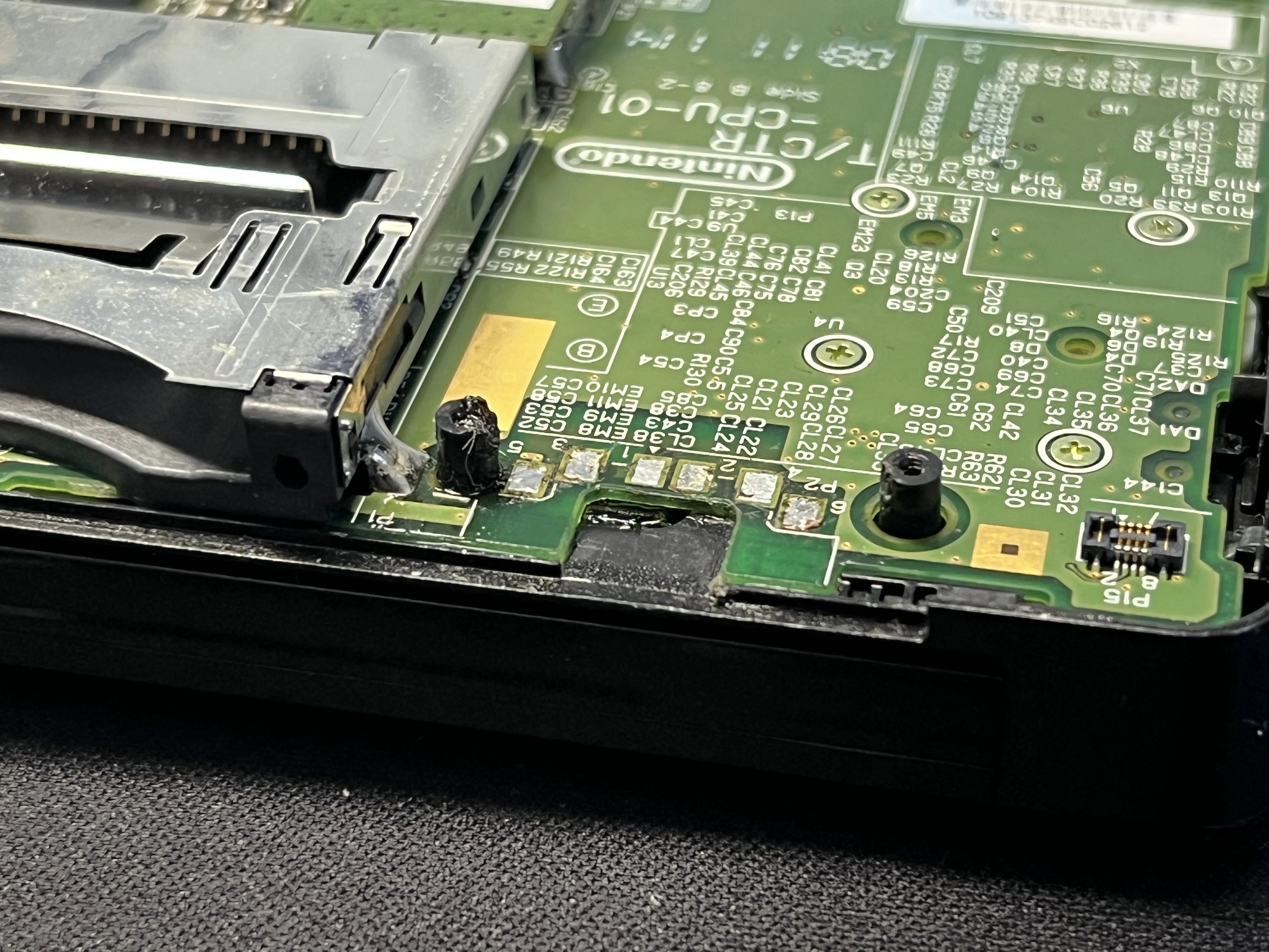
#The USB-C board
Before picking a board to solder onto the 3DS PCB, we need to understand what specifications we are looking for.
#USB Spec
USB-A power supplies traditionally provide 5V on the VBUS power rail.
The amount of current available depends on the port and its charging capabilities, but the voltage itself is fixed at 5V.
USB-C handles this differently. Before a valid connection is established, the power supply keeps VBUS at 0V.
Instead, it monitors two additional pins called CC1 and CC2 (CC stands for Configuration Channel)
to detect connected devices and their power requirements.
Once a valid connection is established, the source enables VBUS and provides the default 5V.
A USB-C device that only requires the default 5V supply implements this using two 5.1k Ohm pull-down resistors, connecting CC1 and CC2 to GND.
These resistors identify the device as a power sink, allowing the charger to detect the connection and enable its default 5V output on VBUS.
Higher voltages like
9V,12V,15V,20Vor even up to48Vwith EPR require additional negotiation using the USB Power Delivery protocol over the CC pins.
Both resistors are necessary because USB-C connectors are reversible.
Depending on the cable orientation, the charger uses either CC1 or CC2 for connection detection.
Having a pull-down resistor on both pins ensures that the device can be detected regardless of how the cable is plugged in.
This also explains why USB-A to USB-C and USB-C to USB-C charging can behave differently.
USB-A to USB-C cables contain a 56k Ohm pull-up resistor in the USB-C plug, connecting VBUS to the CC pin.
This identifies the connection as a legacy USB power source and advertises default 5V USB current to the sink.
With 5V USB-C to USB-C, however, the charger needs to detect one of the 5.1k Ohm pull-down resistors before enabling VBUS.
#3DS Spec
The original Nintendo 3DS charger is rated for 4.6V at 900mA,
At first glance this looks like an issue, as the voltage differs by 0.4V, however 5V is also commonly used by other third-party
3DS charging bricks and cables, so the difference seems to generally be considered safe for the 3DS.
This is outside Nintendo's original charging specification. Compatibility with
5Vis assumed rather than measured :)
It is also important to clear up the misconception that a device always uses the maximum current a power supply can provide. A power supply doesnt force its current into a device, rather the device is pulling whatever it needs from the power supply, assuming the power supply can deliver it. The voltage, on the other hand must remain within the limits of the consoles power handling circuits.
#My board
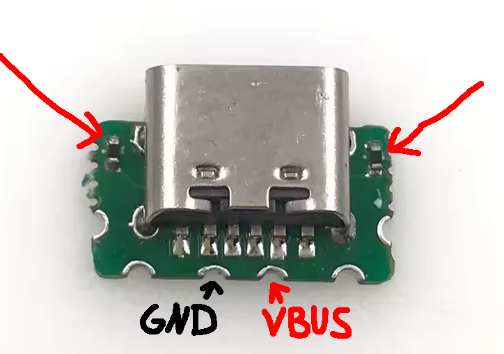
With these requirements in mind, I specifically searched for a 3DS USB-C board with two visible resistors on it, which I found on this USB-C board from AliExpress.
#Install
With the original charging port removed and the pads cleaned up, installing the new board was fairly straightforward.
I soldered the VBUS connection to the right pad and GND to the left pad (it would be really hard to fuck this up unless your port is facing inward).
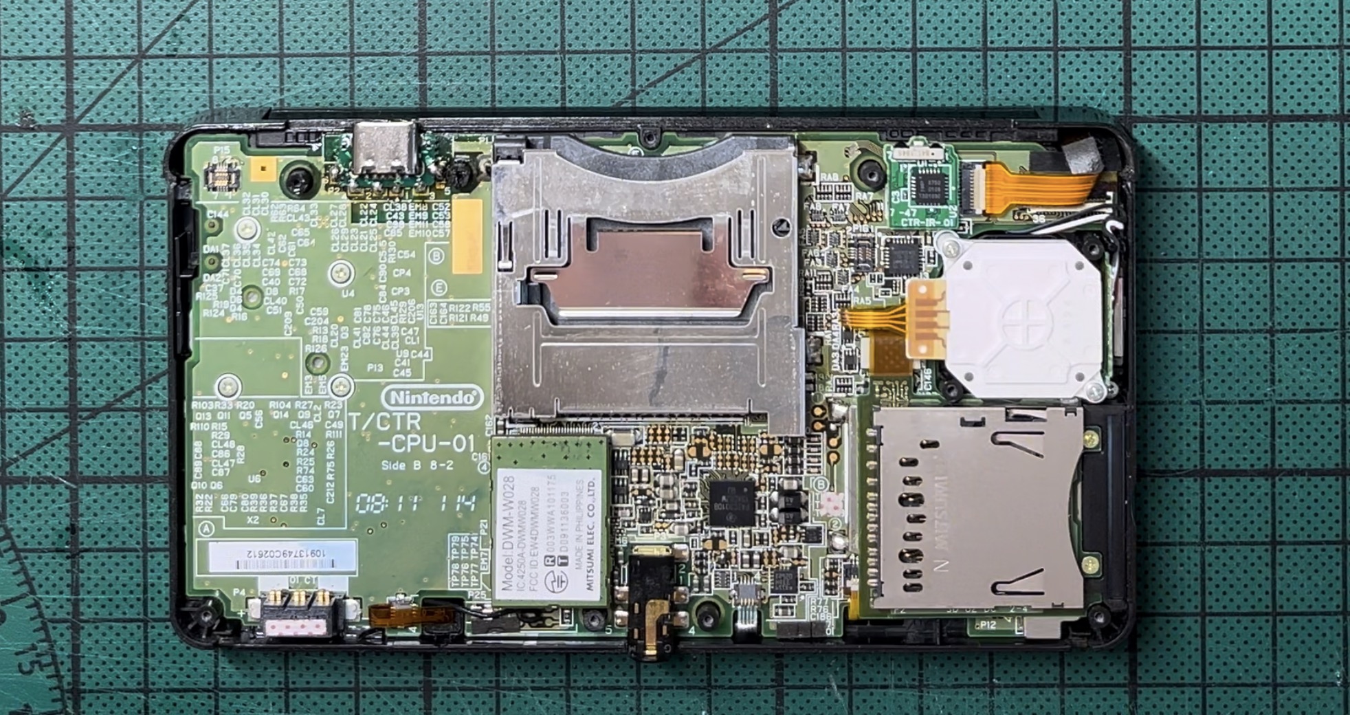
I then tried closing the lower case again, which did not work, as the USB-C port has different dimensions than the original charging port.
A little trimming of the lower shell with a knife (be careful when doing this) was enough to make it fit almost like the original.
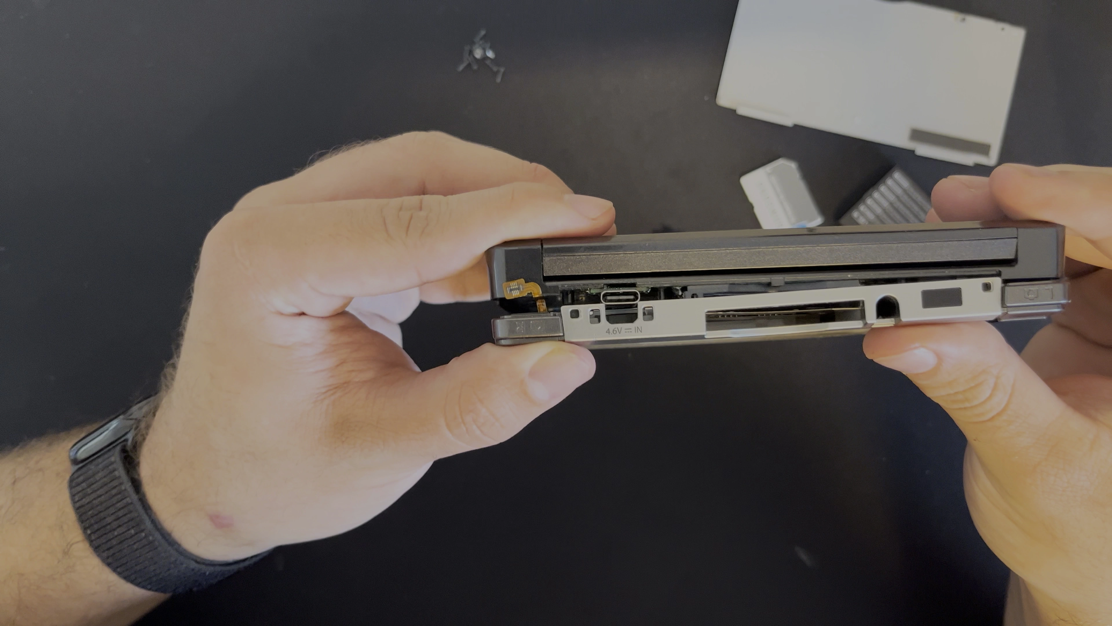
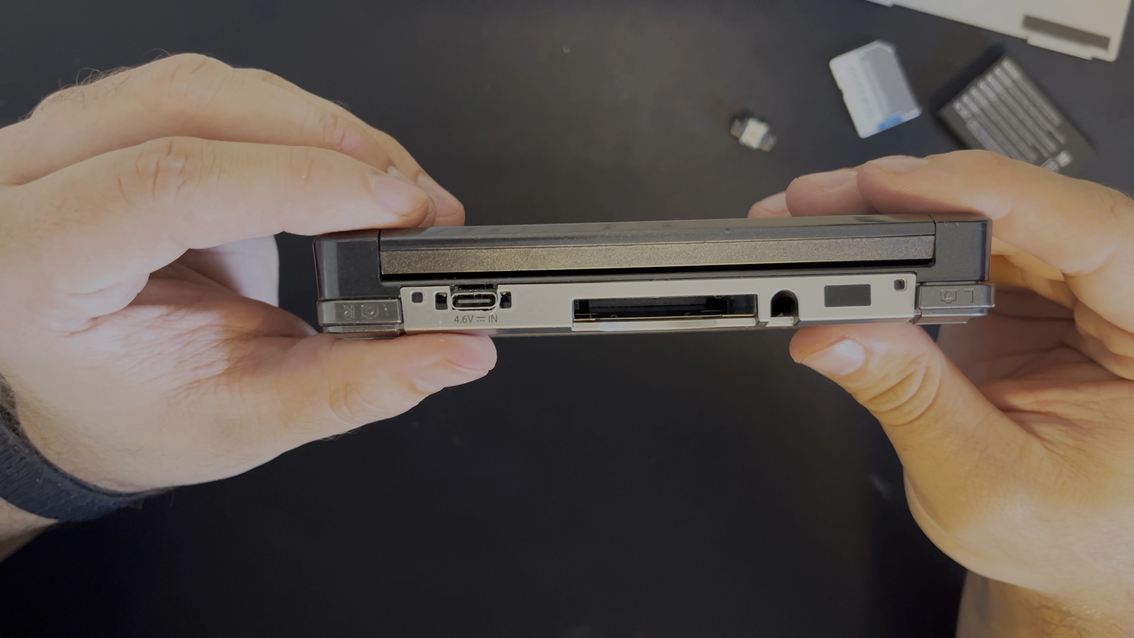
I then reassembled the lower case, reinstalled the battery, and screwed the battery cover back into place.
With everything installed, it was finally time to test whether the connections were correct. Before powering anything on, check whether any solder joint could short something on the board, as that could damage the console beyond repair.
#Testing
First I plugged in a USB-A to USB-C cable, and the 3DS started charging as expected. I was hoping USB-C to USB-C would work too, but on my first try the console only charged briefly, then stopped.
From then on, USB-C to USB-C wouldn't charge at all, while USB-A to USB-C kept working fine.
Initially I suspected that either the board design itself was faulty or that I had made a mistake by not
properly checking the resistors and their connections before installing it.
So I decided to actually measure the resistance of the second USB-C port I had ordered (In case I needed to replace the first one).
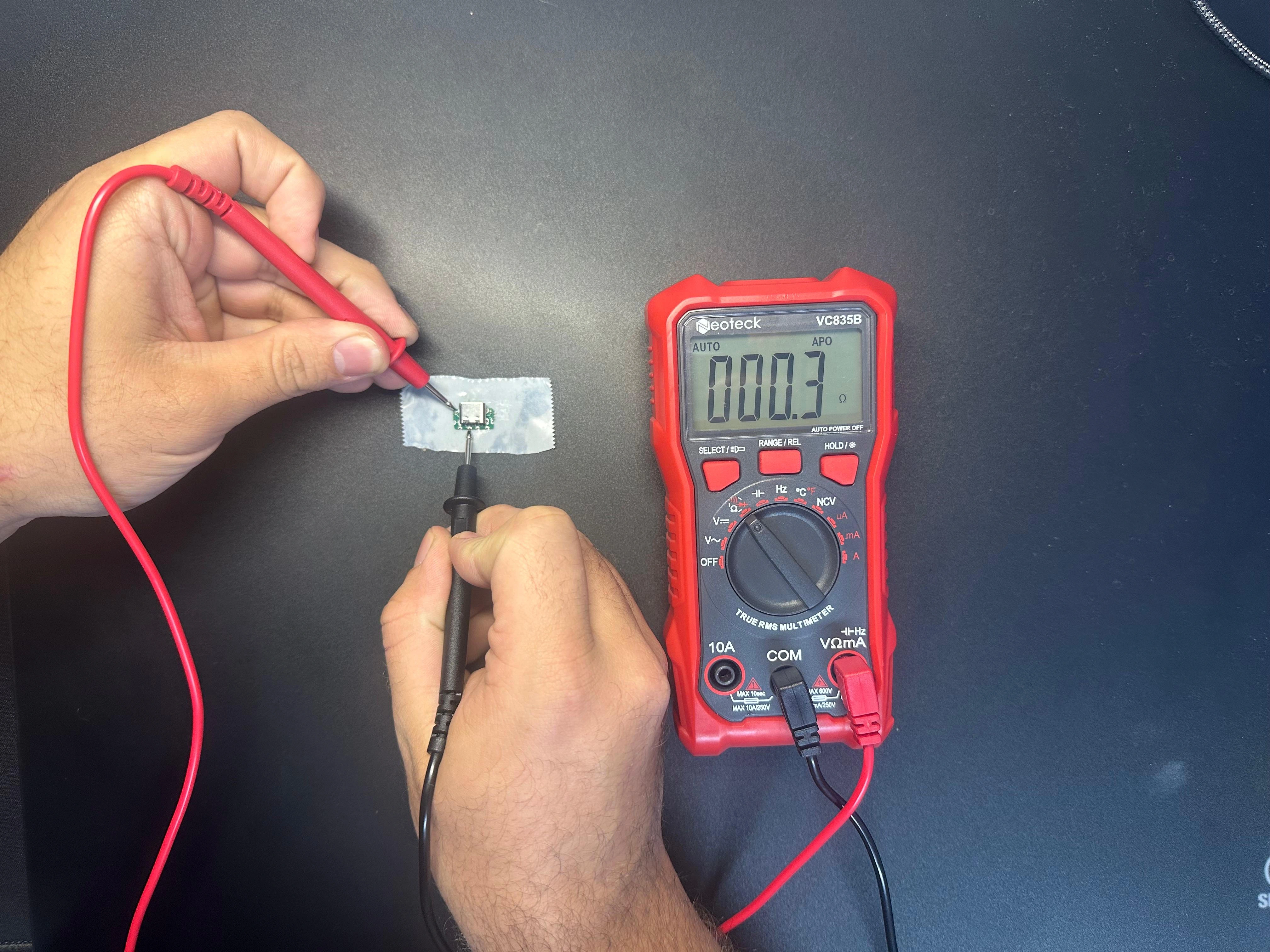
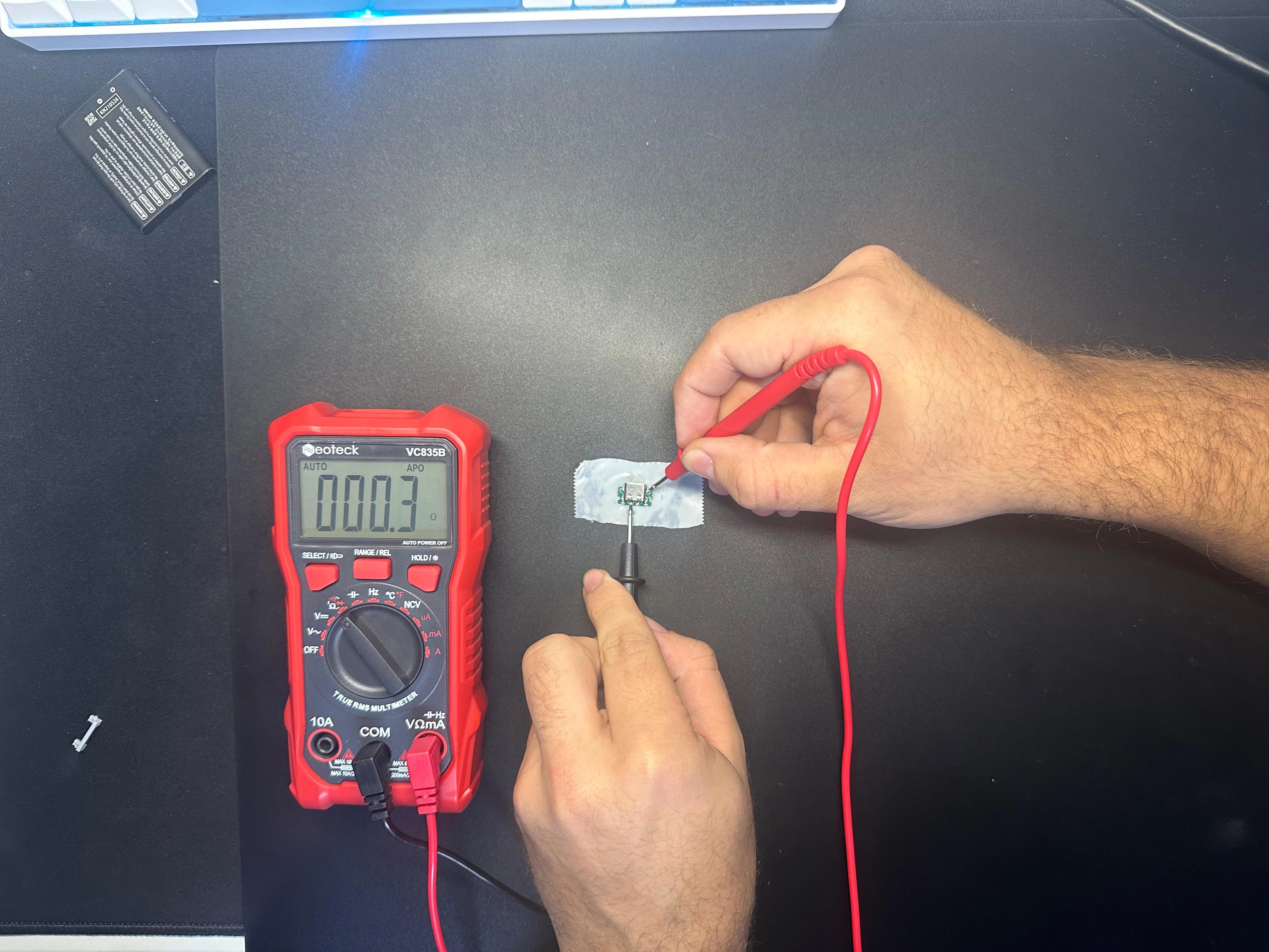
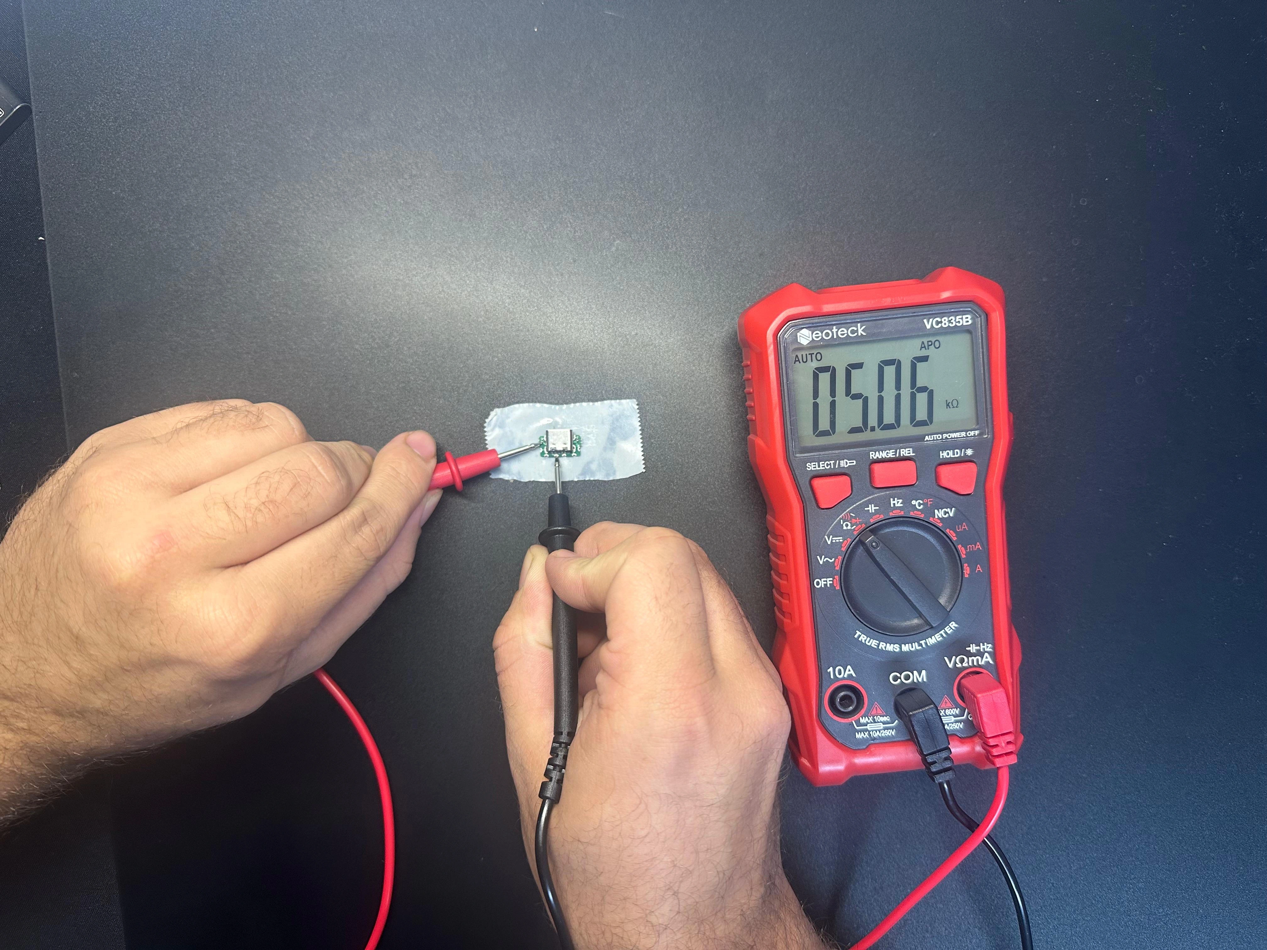
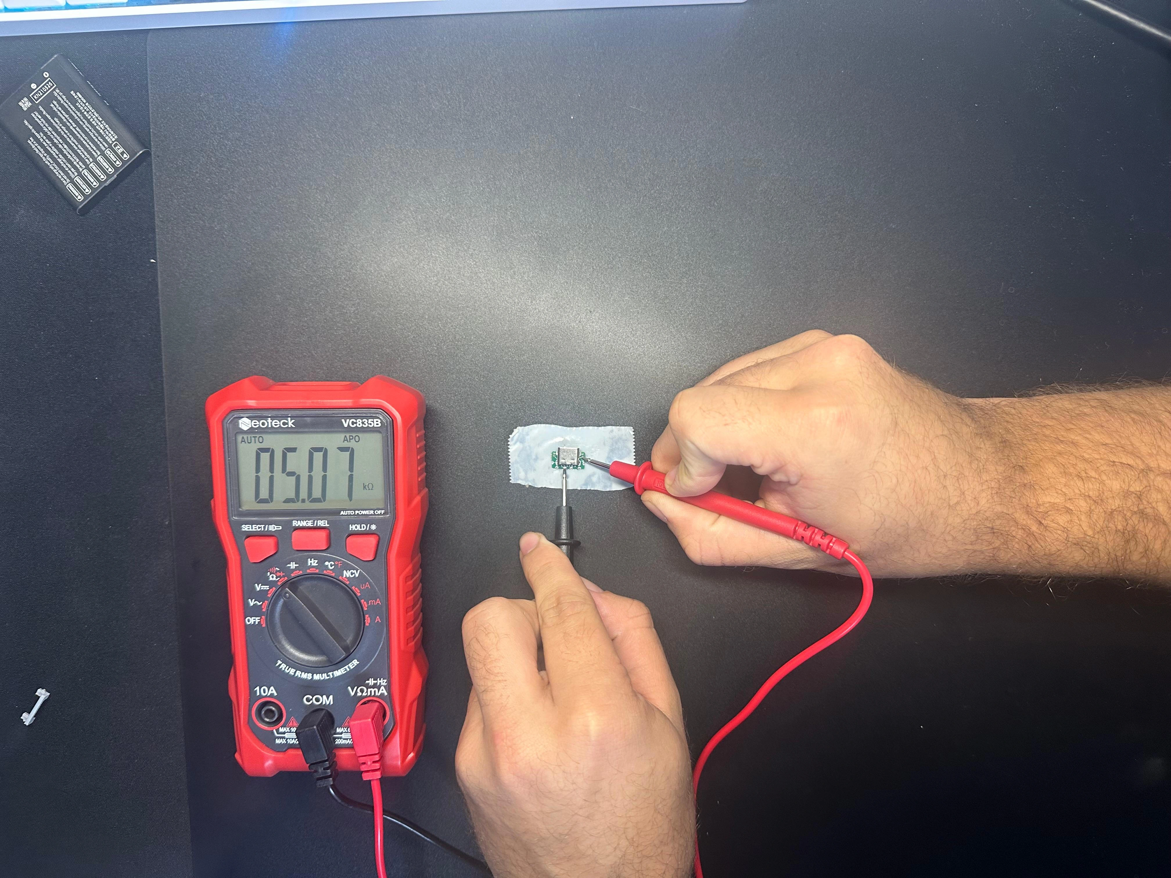
These are the measurements I got:
| Terminal | Resistance |
|---|---|
| Top Left | 0.3 Ohm |
| Top Right | 0.3 Ohm |
| Bottom Left | 5.06k Ohm |
| Bottom Right | 5.07k Ohm |
These values looked perfectly fine and were within the expected range for 5.1k Ohm pull-down resistors:.
The two top terminals measured close to 0 Ohm since they are directly connected to GND, while the bottom terminals were near
the expected 5.1k Ohm.
It took me a surprisingly long time to realize that I hadnt actually tested the USB-C port that I just soldered to the 3DS, and just because the other port had the correct values, I couldnt be sure that the one on the board has those too.
So I opened up the console again, ripping the ribbon cable for the left shoulder button in the process (just like I warned you about earlier).
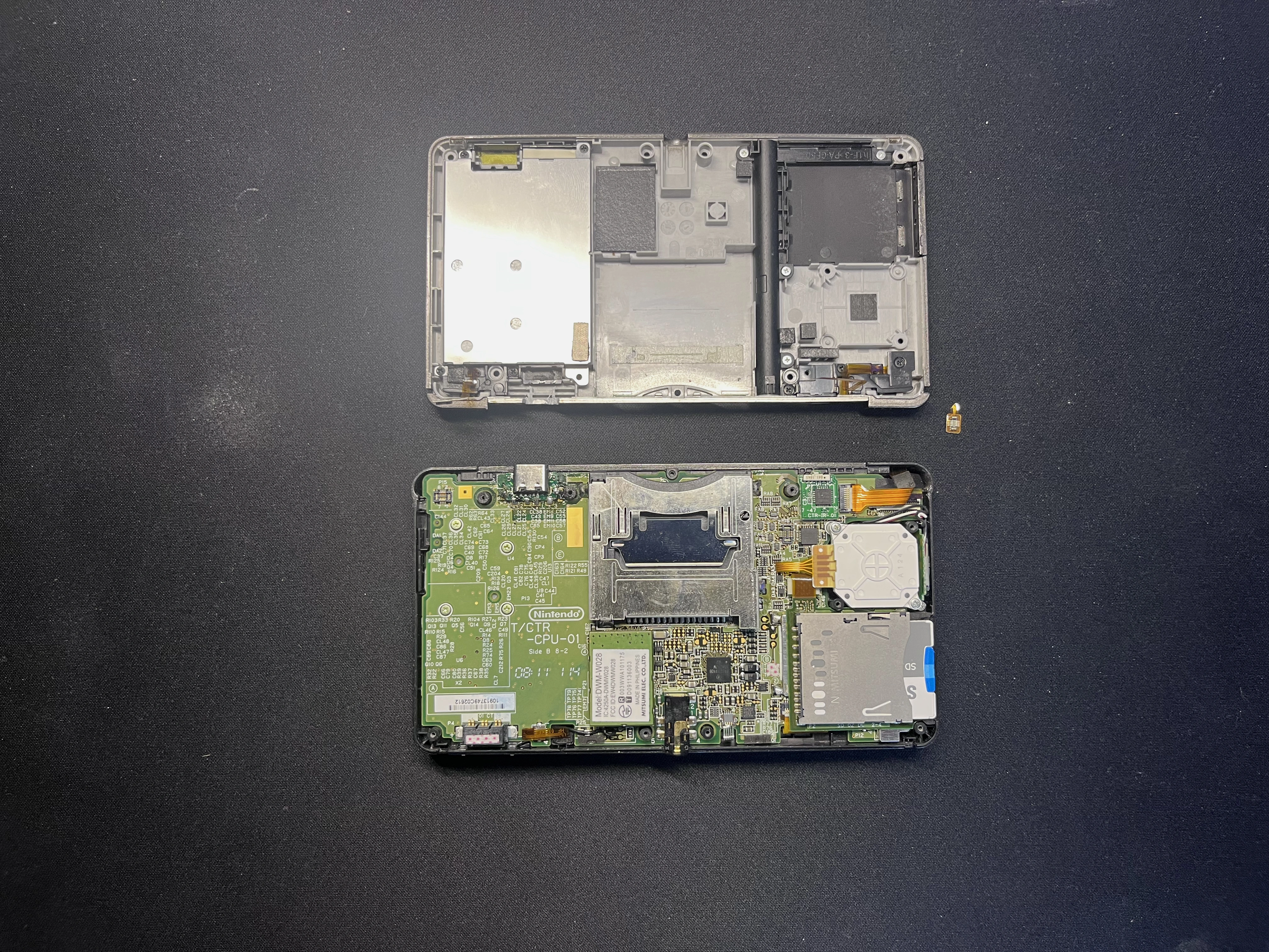
With the console open, I measured the USB-C Port installed on the board itself and got these measurements:
| Terminal | Resistance |
|---|---|
| Top Left | 0.3 Ohm |
| Top Right | 0.3 Ohm |
| Bottom Left | 5.06k Ohm |
| Bottom Right | 0L |
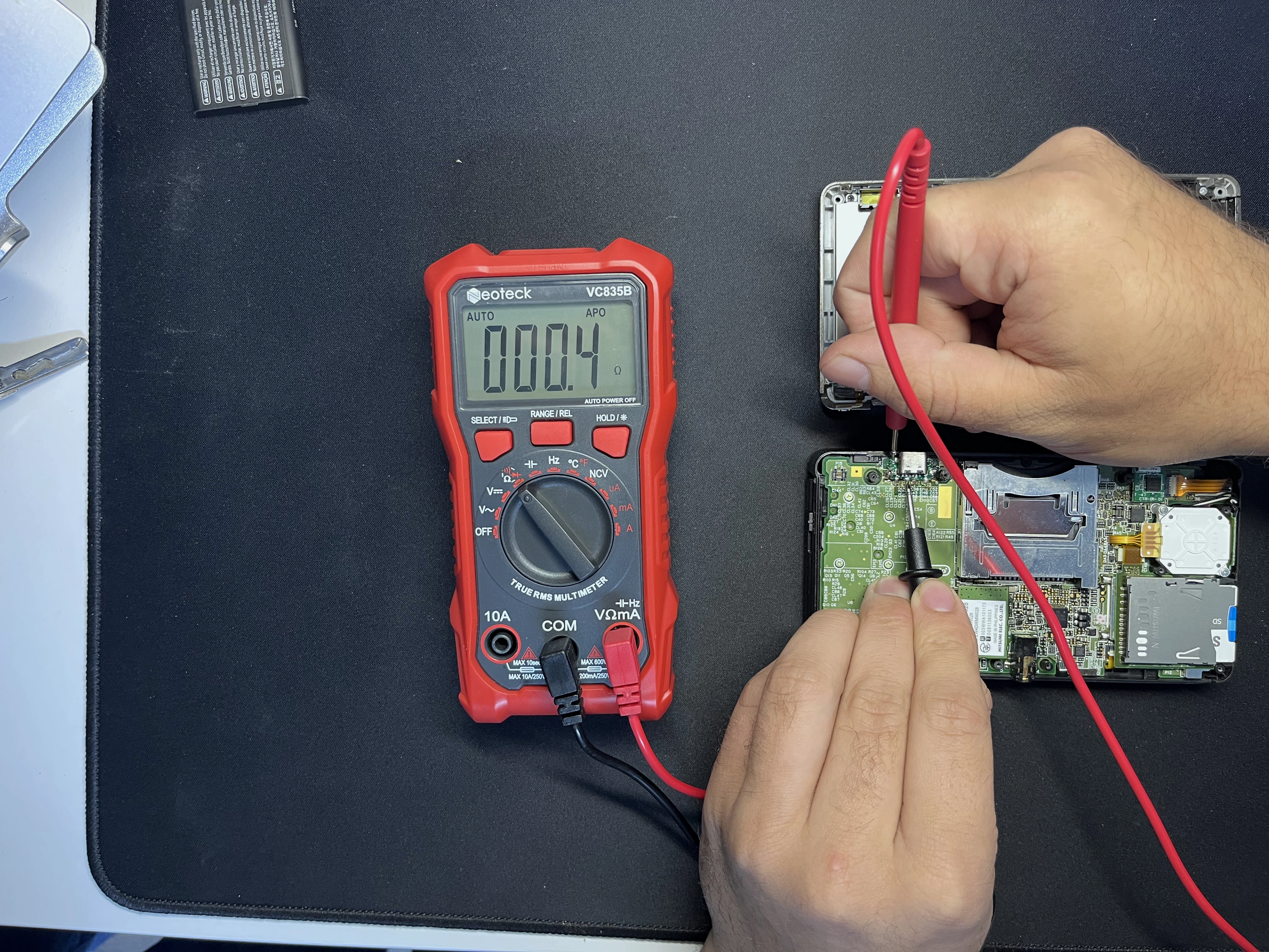
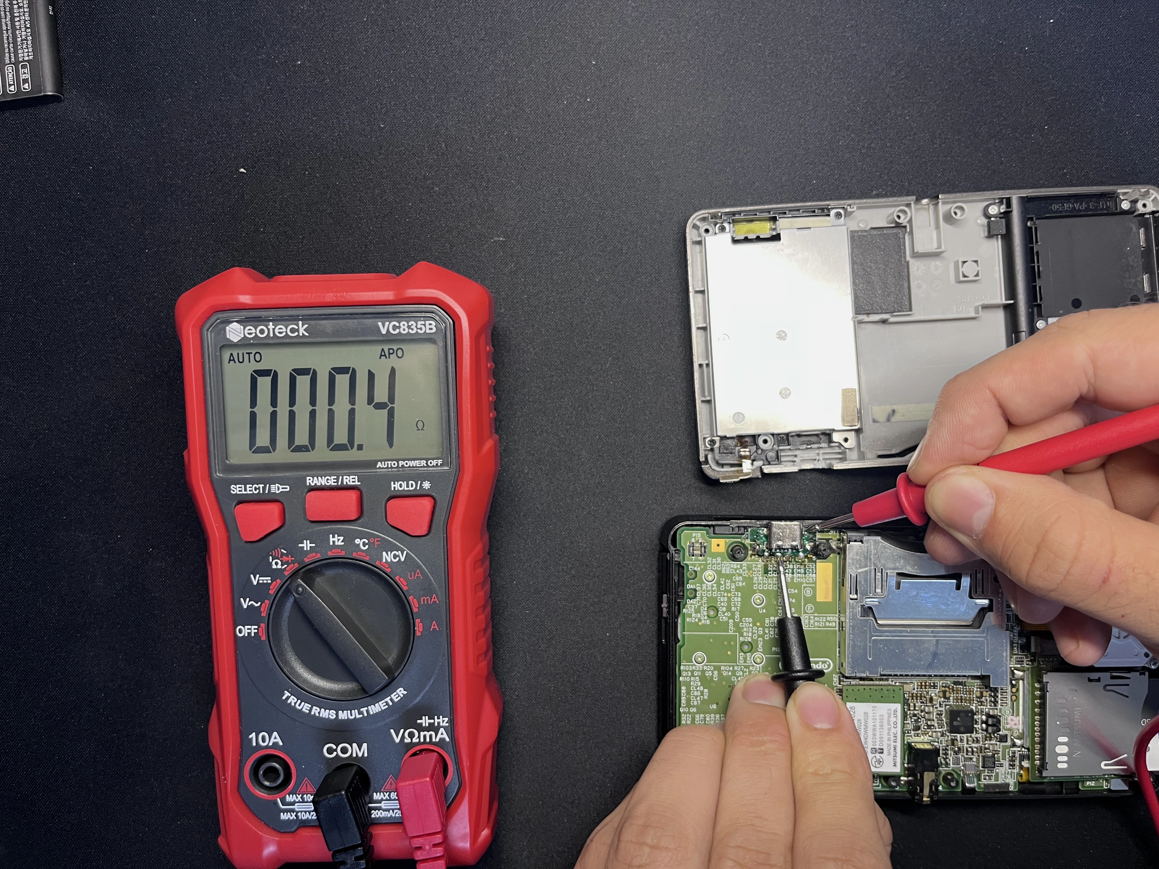
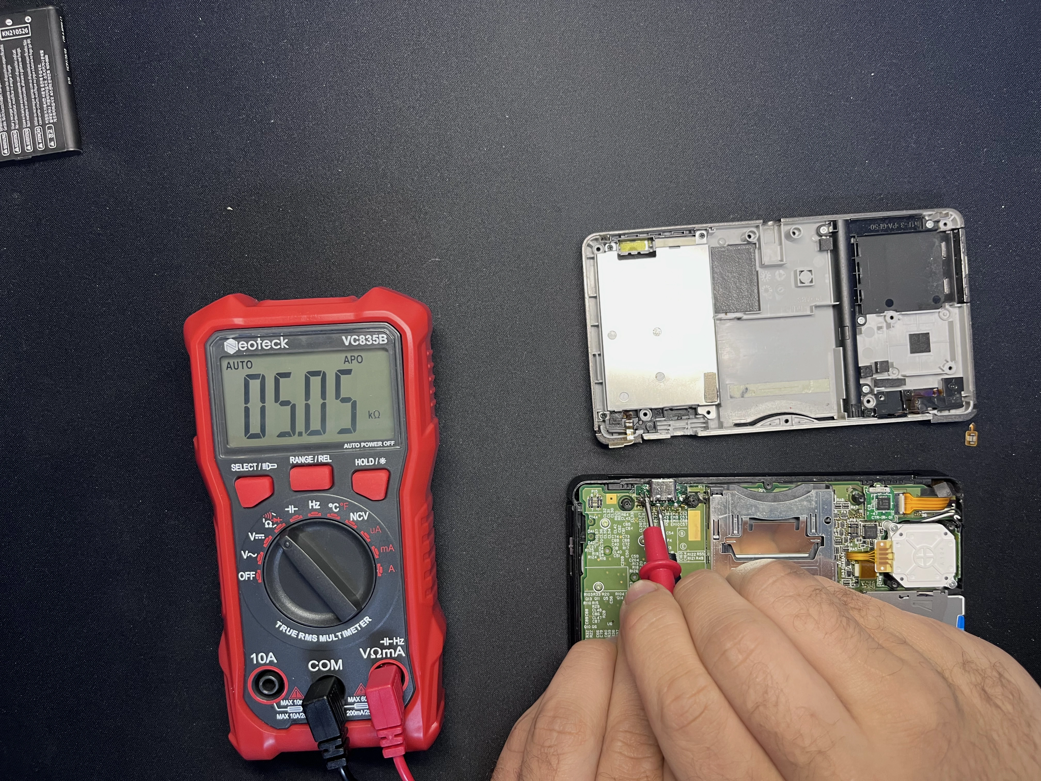
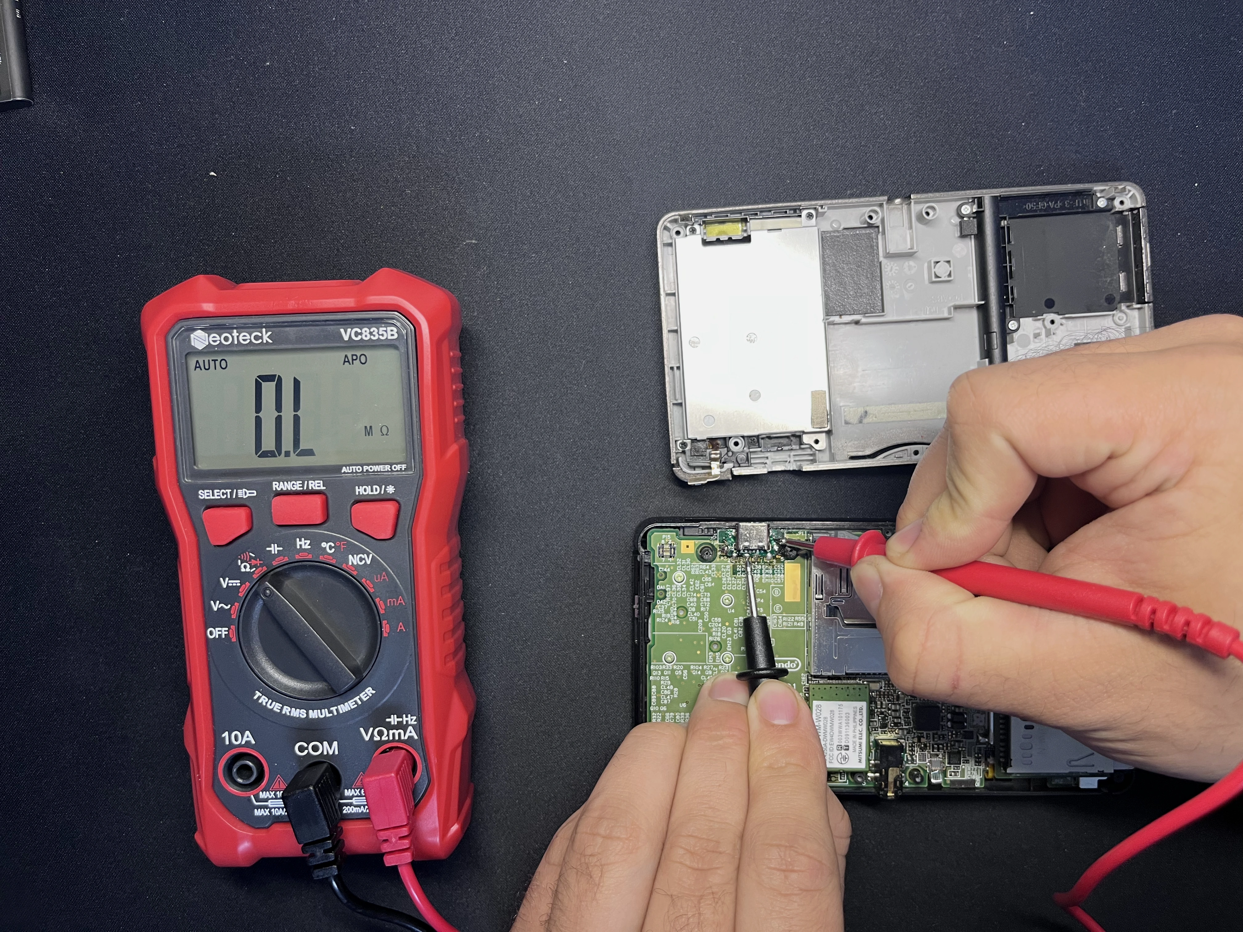
0L indicates an open circuit. In resistance mode, that means the multimeter cant find a path between the two probes.
Here the bottom-right terminal wasn't properly connected to GND, so one of the two CC pull-down resistors
couldnt do its job of communicating with the USB-C power supply.
This could also explain why USB-C to USB-C charging worked on my first attempt but stopped working afterward. Depending on the cable orientation, the charger might initially have used the working CC pin, while all following attempts used the faulty one. I apparently kept plugging the cable in the same orientation afterward :0
At this point I de-soldered the faulty USB-C port and replaced it with the second one, with correct resistance values and connections.
After reassembling the console, I tested USB-A to USB-C charging first, which still worked as expected.
I then plugged a USB-C to USB-C cable into the console which finally worked too!
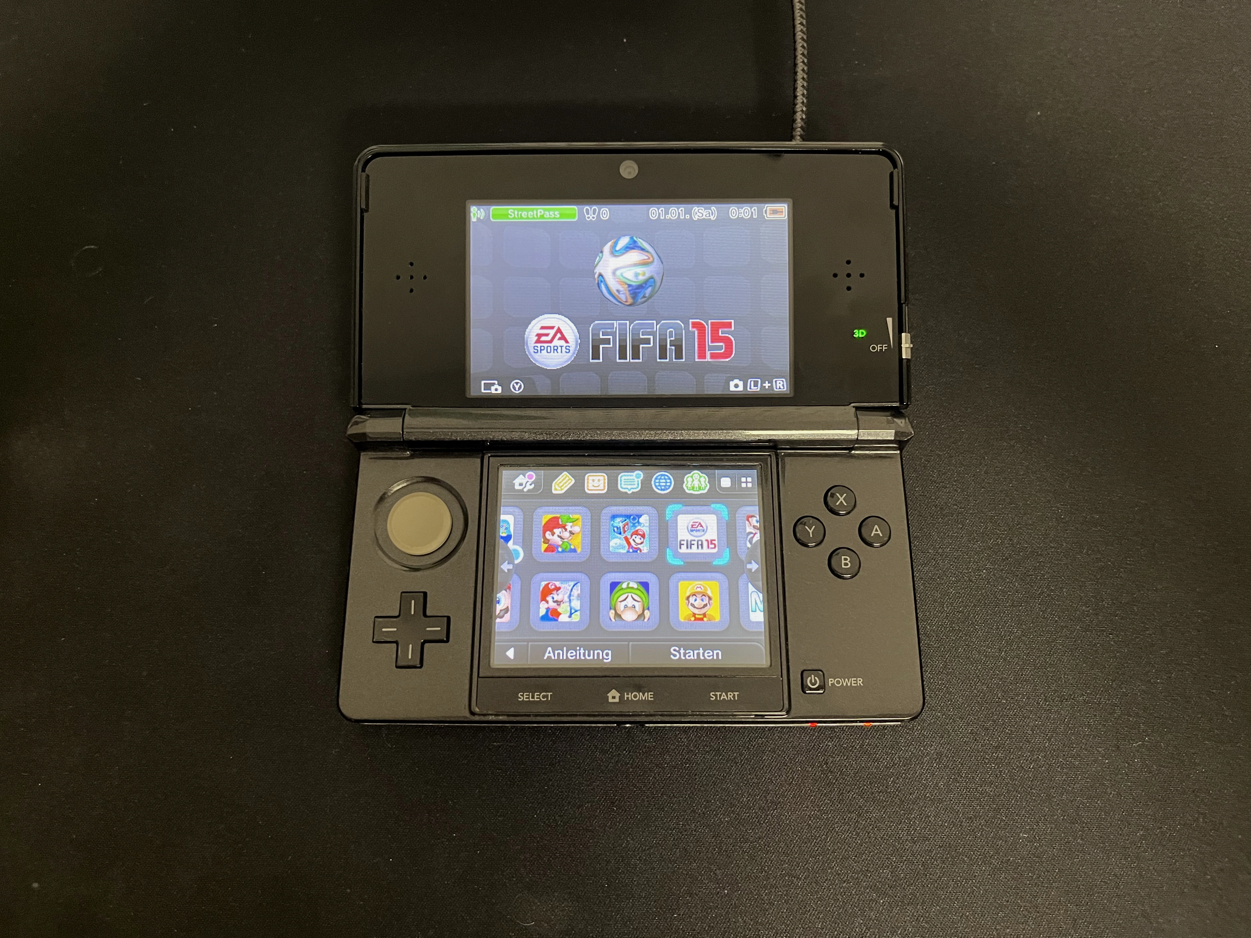
It even works in both orientations 😝